
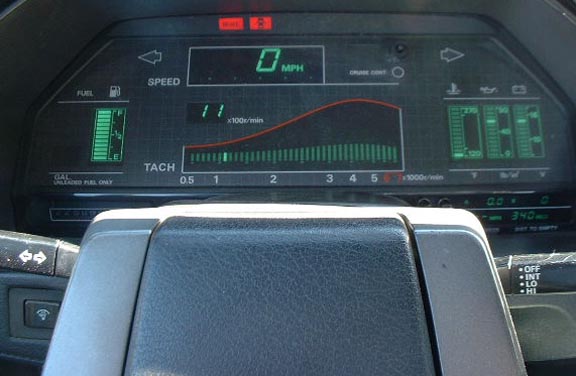
Testen van het Display:
 Wil
je een betere foto, e-mail mij en ik maak een hoge dpi scan voor je.
Wil
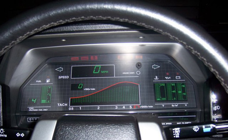
je een betere foto, e-mail mij en ik maak een hoge dpi scan voor je.Digitale Snelheidsmeter geeft de gehele tijd “0” aan:
If the speedometer bar and digital display reads "0" all the time chances are the speed sensor has failed or the speedometer cable has broken. The sensor is assembled and then "potted". That is, the ends are sealed with a black epoxy material which, in theory, should make it weather proof. However, as the epoxy ages, it shrinks, cracks or pulls away from the sensor body. It's only a matter of time before water or salt enters and does the nasty.
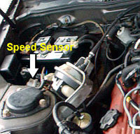
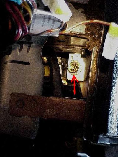
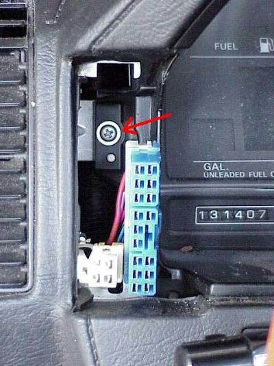
The easiest thing to test is whether or not the cable is good. The speed sensor is a round object mounted to the fender well near the battery with the speedometer cable and red, green, black and yellow wires attached to it (See Image to Right). Remove the cable from the speed sensor first by unscrewing the locking ring. Be sure to watch for a black plastic alignment ring as you pull it apart watch. Don't loose it. Prop the cable up so you can observe the "Square" end of the cable. Put the car in 5th gear and roll the car forwards or backwards 3 or 4 feet. If the cable is good you should see it rotate a half a turn or so. If it turns check the speed sensor next.
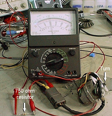
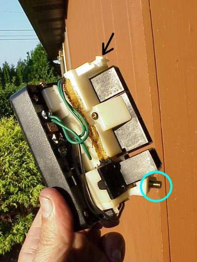
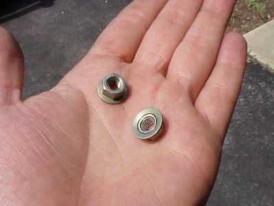
To test the speed sensor you will need small insulated alligator clips, a multi-meter (preferably analog, digital is ok also) and a 5 or 6 volts DC source for bench testing (Click Image at Left). You can use 12 volts from the car battery with a 750 ohm (680-820 will do) current limit resistor in series if the sensor is still in the car. Do not use 12 volts directly! The three wires from the sensor are as follows: BLACK=GROUND, RED=+12VDC, YELLOW=SIGNAL. Attach the alligator clips to the three contacts in the connector ensuring the are not shorting together. Connect the voltage source to the 2 outer clips, ground to black wire and +DC to the red wires. Connect the multi-meter negative to the black wire and positive to the yellow wire. Set the multi-meter to the 10 or 100K ohm range, which ever gives you the best resolution. Slowly turn the shaft of the sensor. If the sensor is good you will see the needle of the sensor swing back and forth. If you are using a digital, the resistance should swing from about 200 ohms to over a meg or infinity. If you have made your connections properly and you see no deflection in the meter, the sensor is likely to be bad.
Digitaal dashboard display (gaat) niet aan:
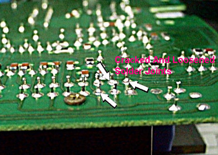
The most common problem is the dash just going out. The power supply unit is the culprit with bad solder joints on the circuit board. Here is the procedure for fixing this problem:
-
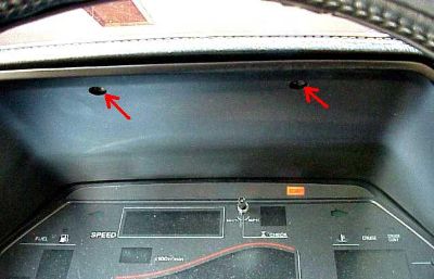
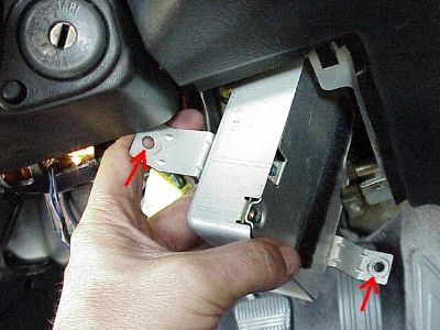
The power supply for the digital dash is located just above your right knee. Remove the trim panel directly above the drivers' knees. It's the one that the hood release and steering wheel tilt lever pass through. ZIE hieronder het hoofdstuk; Verwijder dashboard unit en "Power Supply"
-
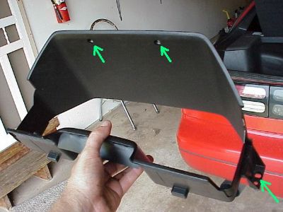
The box is above the area where your right knee is when you're driving. It is about 5x5x1 inches. Remove it by removing the 1-10mm bolt and 1-10mm nut holding the power supply. There are two brackets welded onto it which are held in place by one screw each. There are also two wire harnesses connected to it.
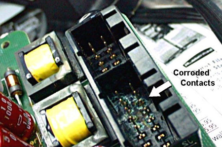
Je kunt gelijk alle corrosie verwijderen die je tegenkomt.
|
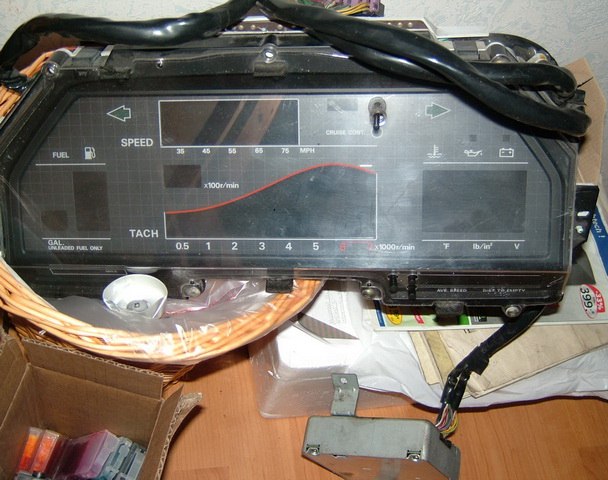
Verwijder dashboard unit en "Power Supply"
Benodigd gereedschap: Wellicht is eerst het stuur demonteren en de stuurschakelaars (zie http://www.nissan300zx.nl/techniek.lichtschakelaar.htm ) makkelijker, maar het schijnt te kunnen zoals hieronder beschreven;
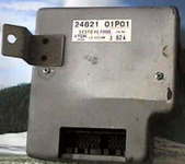
Bovenstaande units 01P01 en 01P11 hebben dezelfde stekkeraansluiting en zijn voor Z31 modellen van '84 t/m '86. (Voor de modellen van '87- '89 geldt een andere stekker aansluiting, hier heb ik geen foto van maar bovenstaande foto's zijn van het oudere model). DAT IS ALTHANS WAT IK MIJ HEB LATEN VERTELLEN!!!! Het onderdeelnummer 24821-01P01 kun je vervangen voor onderdeelnr 24821-01P11.
Of neem een kijkje op zijn website, schrik niet v/d reparatie kosten. Wellicht is een andere unit via E-bay goedkoper... Als alles faalt kun je altijd nog je dashboard ombouwen naar een betrouwbare analoge, zie http://www.nissan300zx.nl/techniek.van.analoog.naar.digitaal.dashboard.htm
|
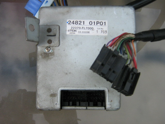 24821-01P01
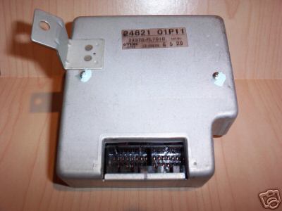 24821-01P11
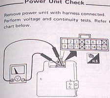 I owned a 1998 300ZX in pristine condition that I considered a hobby car. This
vehicle had an annoying problem with the digital dash. Every time you hit a bump
the display would flicker and sometimes go out.
I owned a 1998 300ZX in pristine condition that I considered a hobby car. This
vehicle had an annoying problem with the digital dash. Every time you hit a bump
the display would flicker and sometimes go out.
 It
was actually over $1000 brand-new from the dealer. I even checked eBay and found
a couple but they were still $500 or more. I decided to disassemble the module
and find out what was wrong with it.
It
was actually over $1000 brand-new from the dealer. I even checked eBay and found
a couple but they were still $500 or more. I decided to disassemble the module
and find out what was wrong with it.